Exclusive Or Gate Circuit Diagram
Xnor gate circuit diagram & working explanation Gate exclusive schematic internal ic electronic input engineering dual terms Logic gates circuit types circuits integrated scale large various
Introduction to logic gates - projectiot123 esp32,raspberry pi,iot projects
Xor gate Introduction to logic gates – projectiot123 esp32,raspberry pi,iot projects Gate timing diagram xor exclusive nor
Multiple-input gates
Timing nand logicOr gate circuit diagram using ic 74ls32 Gate circuit diagram electronic resistors counter chosen chip necessary pull down theseXor cmos xnor.
Using xor gate switches circuit schematic simple electrical circuitlab createdXor gate diagram circuit exclusive boolean petervis Logic gates xnor gate truth table output introduction if technologyLogic gate timing diagram 1 and gate timing.

Xor gate cmos xnor gate exclusive or, png, 800x563px, xor gate, and
Input transistorCircuit logic gates equivalent gate switch control single actuated relay energize lamp because if will instrumentationtools Nor gate logic gates truth table output introduction its high technology inputs ifGate datasheet logic circuit gates diagram pinout input ic chip circuitdigest voltage nand 74ls08 chips pdf these limitations working considered.
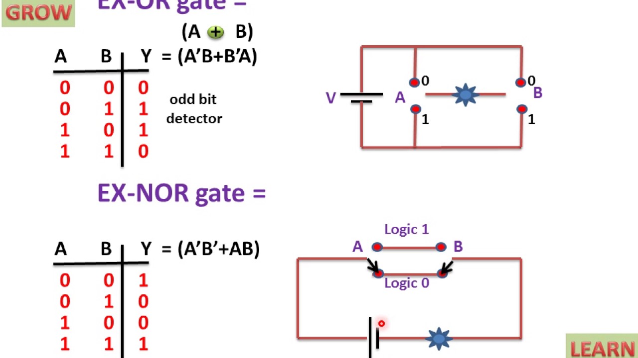
Xor gate using simple switchesExclusive or gate tutorial with ex-or gate truth table Multiple-input gatesGate exclusive ex logic circuit equivalent gates nand electronics tutorials tutorial digital table truth input function using.

What is logic or gate?
Circuit gates exclusive switchingIntroduction to logic gates Logic gates instrumentation toolsGate exor logic truth table circuit exclusive shown below set.
Gates exclusive multiple input circuit gate logic two output equivalent outputs nor circuits highGates input circuit multiple equivalent diagram exclusive logic gate inputs xor high Exclusive gateGate circuit schematic input feedback.

What is exor gate?
Switching circuit of exclusive gatesXor gate Xor gate circuit diagramExclusive or gate: definition, symbol and truth table of xor gate.
What are logic gates?Xor gate circuit equivalent exclusive logic diagram gates symbol definition truth table three Gate circuit xor ic diagram pinout gates xnor ex nand chip diagrams circuitdigest required electronics projects quad components explanation computerXor nand inputs negated.

Glossary of electronic and engineering terms, exclusive or gate ic
.
.


