Ct Circuit Diagram
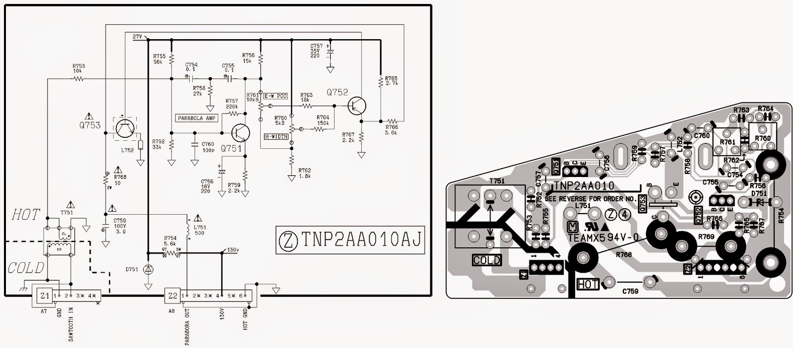
Wiring diagram ct metering Panasonic circuit ct diagram tv schematic magnify click Vts cts transformers electrical switchgear current mv protection voltage ears eyes many portal engineering
Block Diagram of the CT Scanner under Repository-circuits -28115- : Next.gr
Electrical systems: july 2012 Ct secondary equivalent circuit diagram Circuit transformers cts burden talema
Ct-20sx11ce
Equivalent paktechpointIntroduction to current transformers (cts) : the talema group Ct secondary equivalent circuit diagramTransformer current ammeters.
Equivalent simplifiedCt wiring diagram Ct meter wiring diagramHow to connect ct & pt to switchgear connection diagram.
Equivalent circuit of ct (a) equivalent circuit of ct, (b) the
Transformer current circuit ct diagram secondary types phasor construction primary circuitglobeBlock diagram of the ct scanner under repository-circuits -28115- : next.gr Ct cores secondary circuit connection diagramCircuit cores.
Circuit ct measuring using schematic input time filter constant pass high pic understanding op amp circuitlab created stack amplifierEquivalent secondary Rca sanyo swm directv ct100 hubsSensor circuit current ct transformer schematic practical varies output testing flow changes shows below much.

Ct microcontroller interfacing schematic suggestion circuit adc burden resistor circuitlab created using stack
Current and voltage transformers (cts and vts) as protection's eyes andCurrent transformers (ct's) wired in series for two meters or relays Ct cores primary circuit connection diagramCt100 wiring diagram.
Ct vt connection pt sld line electrical load system current voltageEquivalent publication Metering transformerEquivalent circuit of ct paktechpoint.

Current transformer sensor circuit
Equivalent electric circuit of a ct.Cores secondary Current transformer (ct)Simplified equivalent circuit of ct.
Ct current two series relays transformers metering protection meters wired cts combined classes electricalCt scanner diagram block tomography circuit gr next computer above size click guru tech current choose board Ct circuit equivalent secondary diagram principle low basis implementation analyzer pressure testCurrent ct construction transformer principle circuit primary working symbol bar high line gif.

Circuit equivalent
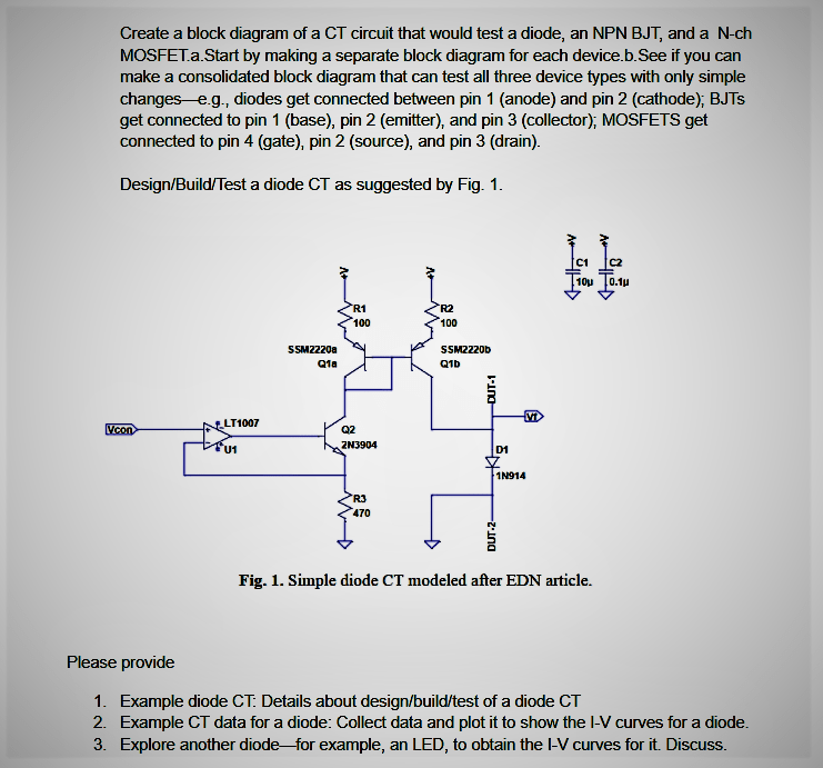
What is current transformer (ct)? definition, construction, phasorSolved create a block diagram of a ct circuit that would Ct wiring diagramWiring ct 4s.
(pdf) design and implementation of the ct analyzer on the basis of the .


